Zener diodes find wide applications commercially and industrially. Some of the important applications of a Zener Diodes are as a Voltage Regulator or Stabilizer, as a Meter Protector and as a Wave-Shaper. They are discussed below in detail.
As a Voltage Stabilizer
The major application of a Zener diode in the electronic circuit is as a Voltage Regulator. It provides a constant voltage to the load from a source whose voltage may vary over a sufficient range.
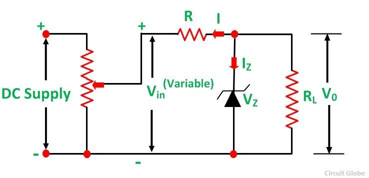
The figure below shows the circuit arrangement of the Zener diode as a regulator.
 In the above circuit, the Zener diode of Zener Voltage VZ is connected across the load RL in reverse condition. The constant voltage (V0 = VZ) is the desired voltage across the load. The output voltage fluctuation is absorbed by a series resistor R which is connected in series with the circuit. This maintains a constant voltage (V0) across the load.
Let a variable voltage Vin be applied across the load RL. When the value of Vin is less than Zener voltage VZ to the Zener diode no current flows through it and the same voltage appearing across the load. The Zener diodes conduct a large current when the input voltage Vin is more than the Zener Voltage Vz. As a result, a large amount of current flows through series resistor R which increases the voltage drop across it.
Thus, the input voltage, excess of Vz (i.e. Vin – VZ) is absorbed by the series resistor. Hence, a constant voltage V0 = Vz is maintained across the load RL. When a Zener diode of Zener voltage Vz is connected in the reverse direction parallel to the load, it maintains a constant voltage across the load equal to Vz and hence stabilizes the output voltage.
For Meter Protection
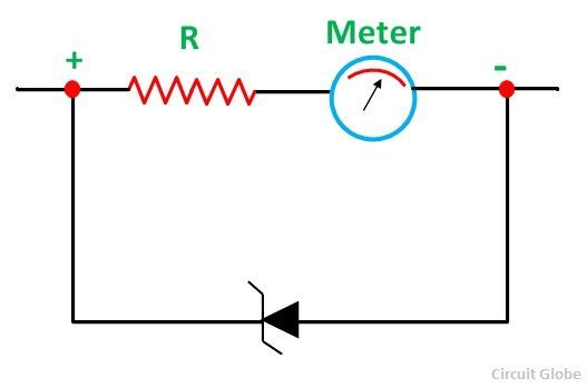
Zener diodes are generally employed in multimeters to protect the meter movement against the damage from the accidental overloads. The Zener diode is connected in parallel with the meter from the safety point of view.
The circuit diagram is shown below:
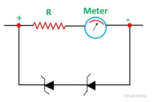
 The Meter movement is protected from any damage as most of the current passes through the Zener diode, in case of any accidental overload. When the meter movement is required to be protected, regardless of the applied polarity (i.e when an alternating current is passed).
The circuit arrangement is modified as shown in the figure below:
 For Wave Shaping
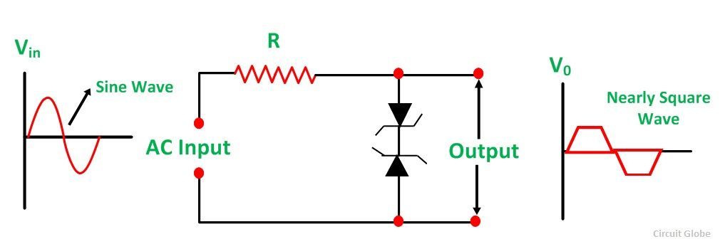
Zener diodes are also used to convert sine wave into square waves. The circuit arrangement is shown below:
 During the positive and negative half cycle, when the voltage across the diodes is below Zener value they offer a high resistance path. The input voltage appearing across the output terminals. However, when the input voltage increases beyond the Zener value, the Zener diode offers a low resistance path and conduct large current.
As a result, a heavy voltage drop appears across the series resistor R and hence the peaks of the input wave are clipped off when appearing at the output as shown in the above figure. The input sine wave is clipped off at the peaks and a square wave appears at the output.

Nice…..
good explanation
Hello,
Great explanation! I have 1 question though. In the example of the meter protection it states that most of the current will flow through the zener diode, why? why will omst of the current flow through the zener? Can you please give an explanation of this and maybe include some calculations?
Thank you and love your website!