The electrical system is of two types i.e., the single-phase system and the three-phase system. The single-phase system has only one phase wire and one return wire thus it is used for low power transmission.
The three-phase system has three live wire and one returns the path. The three-phase system is used for transmitting a large amount of power. The 3 phase system is divided mainly into two types. One is a balanced three-phase system and another one is an unbalanced three-phase system.
Contents:
- Analysis of Balanced 3 Phase Circuit
- Analysis of Unbalanced 3 Phase Circuit
- Interconnection of 3 Phase System
- Connection of 3 Phase Loads in 3 Phase System
The balance system is one in which the load are equally distributed in all the three phases of the system. The magnitude of voltage remains same in all the three phases and it is separated by an angle of 120º.
In the unbalance system the magnitude of voltage in all the three phases becomes different.
Analysis of Balanced 3 Phase Circuit
It is always better to solve the balanced three-phase circuits on the basis of each phase. When the three-phase supply voltage is given without reference to the line or phase value, then it is the line voltage which is taken into consideration.
The following steps are given below to solve the balanced three-phase circuits.
Step 1 – First of all draw the circuit diagram.
Step 2 – Determine XLP = XL/phase = 2πfL.
Step 3 – Determine XCP = XC/phase = 1/2πfC.
Step 4 – Determine XP = X/ phase = XL – XC
Step 5 – Determine ZP = Z/phase = √R2P + X2P
Step 6 – Determine cosϕ = RP/ZP; the power factor is lagging when XLP > XCP and it is leading when XCP > XLP.
Step 7 – Determine the V phase.
For star connection VP = VL/√3 and for delta connection VP = VL
Step 8 – Determine IP = VP/ZP.
Step 9 – Now, determine the line current IL.
For star connection IL = IP and for delta connection IL = √3 IP
Step 10 – Determine the Active, Reactive and Apparent power.
Analysis of Unbalanced 3 Phase Circuit
The analysis of the 3 Phase unbalanced system is slightly difficult, and the load is connected either as Star or Delta. The topic is discussed in detail in the article named as Star to Delta and Delta to Star Conversion.
Interconnection of 3 Phase System
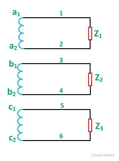
In a three-phase AC generator, there are three windings. Each winding has two terminals (start and finish). If a separate load is connected across each phase winding as shown in the figure below, then each phase supplies as independent load through a pair of wires. Thus, six wires will be required to connect the load to a generator. This will make the whole system complicated and costly.
Therefore, in order to reduce the number of line conductors, the three-phase windings of an AC generator are interconnected. The interconnection of the windings of a three-phase system can be done in the following two ways:
Star or Wye (Y) connection Also See: Star Connection in 3 Phase System
Mesh or Delta (Δ) connection. Also See: Delta Connection in 3 Phase System
Connection of 3 Phase Loads in 3 Phase System
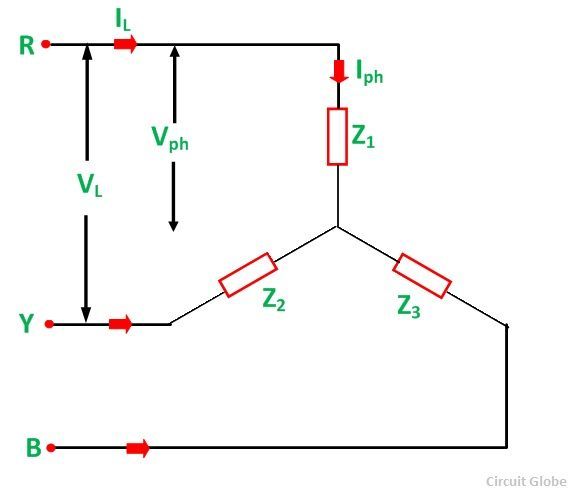
As the three-phase supply is connected in star and delta connections. Similarly, the three-phase loads are also connected either as Star connection or as Delta Connection. The three-phase load connected in the star is shown in the figure below:
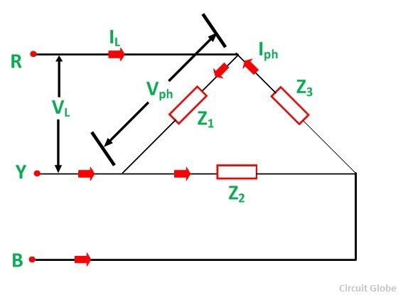
 The delta connection of three-phase loads is shown in the figure below:
 The three-phase loads may be balanced or unbalanced as discussed above. If the three loads Z1, Z2 and Z3 have the same magnitude and phase angle, then the 3 phase load is said to be a balanced load. Under such connections, all the phase or line currents and all the phase or line voltages are equal in magnitude.

