A bus in a power system is defined as the vertical line at which the several components of the power system like generators, loads, and feeders, etc., are connected. The buses in a power system are associated with four quantities. These quantities are the magnitude of the voltage, the phase angle of the voltage, active or true power and the reactive power.
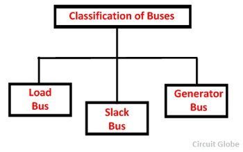
In the load flow studies, two variable are known, and two are to be determined. Depends on the quantity to be specified the buses are classified into three categories generation bus, load bus and slack bus.
 The table shown below shows the types of buses and the associated known and unknown value.
| Type of Buses | Know or Specified Quantities | Unknown Quantities or Quantities to be determined. |
|---|---|---|
| Generation or P-V Bus | P, | V | | Q, δ |
| Load or P-Q Bus | P, Q | | V |, δ |
| Slack or Reference Bus | | V |, δ | P, Q |
Generation Bus or Voltage control bus
This bus is also called the P-V bus, and on this bus, the voltage magnitude corresponding to generate voltage and true or active power P corresponding to its rating are specified. Voltage magnitude is maintained constant at a specified value by injection of reactive power. The reactive power generation Q and phase angle δ of the voltage are to be computed.
Load Bus
This is also called the P-Q bus and at this bus, the active and reactive power is injected into the network. Magnitude and phase angle of the voltage are to be computed. Here the active power P and reactive power Q are specified, and the load bus voltage can be permitted within a tolerable value, i.e., 5 %. The phase angle of the voltage , i.e.δ is not very important for the load.
Slack, Swing or Reference Bus
Slack bus in a power system absorb or emit the active or reactive power from the power system. The slack bus does not carry any load. At this bus, the magnitude and phase angle of the voltage are specified. The phase angle of the voltage is usually set equal to zero. The active and reactive power of this bus is usually determined through the solution of equations.
The slack bus is a fictional concept in load flow studies and arises because the I2R losses of the system are not known accurately in advance for the load flow calculation. Therefore, the total injected power cannot be specified at every bus. The phase angle of the voltage at the slack bus is usually taken as reference or zero

Very Good site. Everything is in very proper manner. I found the solution of my many doubt here.
It really cleared my confusion and explained very good all the concepts.
Thanks for building this site. this site has helped me a lot for my exams preparation.
With regards,
SPARSH Pandey
Very good explanation
Really very clear concept in a concise manner👌
Very helpful … thanks
Good work . Hoping to learn more .