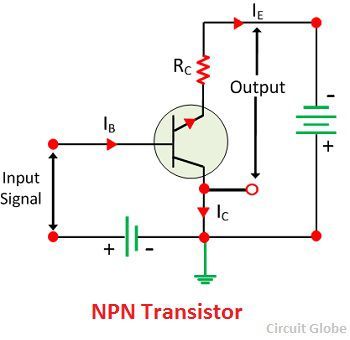
Definition: The configuration in which the collector is common between emitter and base is known as CC configuration. In CC configuration, the input circuit is connected between emitter and base and the output is taken from the collector and emitter. The collector is common to both the input and output circuit and hence the name common collector connection or common collector configuration.
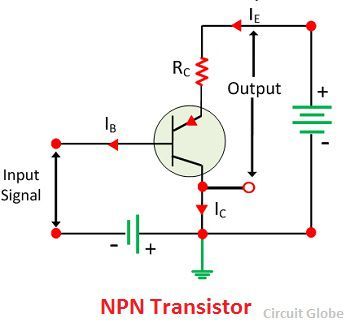 Current Amplifier Factor (Y)
The current amplification factor is defined as the ratio of the output current to the input current. In common emitter configuration, the output current is emitter current IE, whereas the input current is base current IB.
Thus, the ratio of change in emitter current to the change in base current is known as the current amplification factor. It is expressed by the Y.
 Relation Between Υ and α
The Y is the current amplification factor of common collector configuration and the α is current amplification factor of common base connection.
 and,
and, 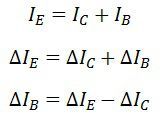 Substituting the value of ΔIB in above first equation, we get,
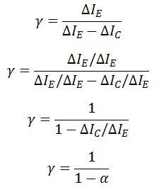 The above relation shows that the value of Y is nearly equal to β. This circuit is mainly used for amplification because of this arrangement input resistance is high, and output resistance is very low. The voltage gain of the resistance is very low. This circuit arrangement is mainly used for impedance matching.
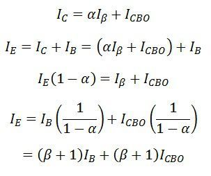
Collector Current
We know that,
 Input Characteristic Curve
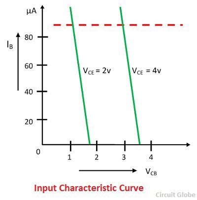
The input characteristic of the common collector configuration is drawn between collector base voltage VCE and base current IB at constant emitter current voltage VCE. The value of the output voltage VCE changes with respect to the input voltage VBC and IB With the help of these values, input characteristic curve is drawn. The input characteristic curve is shown below.
 Output Characteristic Curve
The output characteristic of the common emitter circuit is drawn between the emitter-collector voltage VEC and output current IE at constant input current IB. If the input current IB is zero, then the collector current also becomes zero, and no current flows through the transistor.
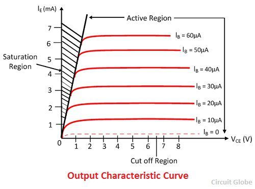 The transistor operates in active region when the base current increases and reaches to saturation region. The graph is plotted by keeping the base current IB constant and varying the emitter-collector voltage VCE, the values of output current IE are noticed with respect to VCE. By using the VCE and IE at constant IB the output characteristic curve is drawn.

The content is really helpful!!