Definition: The current source inverter converts the input direct current into an alternating current. In current source inverter, the input current remains constant but this input current is adjustable. The current source inverter is also called current fed inverter. The output voltage of the inverter is independent of the load. The magnitude and nature of the load current depends on the nature of load impedance.
Current Source Inverter Control
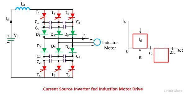
A thyristor current source inverter is shown in the figure below. The diodes D1-D6 and capacitor C1-C6 provide commutation of thyristor T1-T6, which are fired with a phase difference of 60º in the sequence of their number. It also shows the nature of the output current waveform. The inverter act as a current source due to large inductance LD in DC link. The fundamental component of motor phase current is shown in the figure below.
 The torque is controlled by varying DC link current Id by changing the value of Vd. When the supply is AC, a controlled rectifier is connected between the supply and inverter. When the supply is, DC a chopper is interposed between the supply and inverter.
 The major advantage of current source inverter is its reliability. In the case of current source inverter a commutation failure in the same leg does not occur due to the presence of a large inductance Ld.
In an induction motor, the rise and fall of current are very fast. This rise and fall of current provide large motor spikes. Therefore a motor of low leakage inductance is used. The commutation capacitance C1-C6 reduce the voltage spikes by reducing the rate of rising and fall of the current. A large value of capacitance is required to sufficiently reduced the voltage spikes.
Regenerative braking and Multiquadrant Operation of CSI
When the motor speed is less than the synchronous speed, machine work as a generator. The power flows from machine to DC link and DC link voltage Vd reverse. If a fully controlled converter is made to work as an inverter, then the power supply to DC link will be transferred to AC supply, and regenerative braking will take place. Hence no additional equipment is required for regenerative braking of DC motor drive.
The drive can have regenerative braking capability and four quadrant operation if a two-quadrant chopper provides current in one direction, but voltage in either direction is used.
Closed Loop Speed Control of CSI Drives
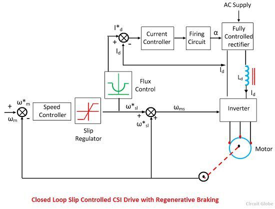
The closed loop CSI drive is shown is shown in the figure below. The actual speed ωm is compared with the reference speed ω*m. The speed error is controlled through PI controller and slip regulator. The slip regulator sets the slips speed command ω*sl. The synchronous speed obtained by adding ωm, ω*sl determines the inverter frequency.
Constant flux is obtained when slip speed ωsl and Is have the relationship. Since Id is proportional to Is, according to the equation shown below a similar relation exists between ωsl and Id for constant flux operation.
 Based on the value of ω*sl, the flux control flux produces a common reference current I*d, which through a closed loop current control adjust the DC link current Id to maintain a constant flux. The limit imposed on the output of slip regulator, limit Id at the inverter rating flux. Therefore, any correction in speed error is carried out at the maximum permissible inverter current and maximum available torque, giving a fast transient response and current protection.

I need control system notes and power electronics notes according a.m.i.e syllabus