In the medium and long transmission lines inductance (reactance) is more effective than resistance. The current flow in the transmission line interacts with the other parameter, i.e the Inductance. We know that when current flow within a conductor, magnetic flux is set up. With the variation of current in the conductor, the number of lines of flux also changes, and an emf is induced in it (Faraday’s Law). This induced emf is represented by the parameter known as inductance.
The flux linking with the conductor consist of two parts, namely, the internal flux and the external flux. The internal flux is induced due to the current flow in the conductor. The external flux produced around the conductor is due to its own current and the current of the other conductors place around it. The total inductance of the conductor is determined by the calculation of the internal and external flux.
Inductance of a two-wire line
Considered a single phase line consisting of two conductors (phase and neutral) a and b of equal radius r. They are situated at a distance D meters. The cross sections of conductors are shown in the diagram below.
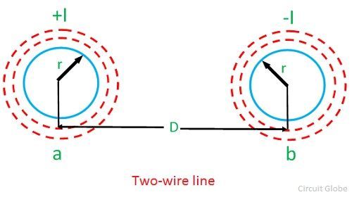 Let the current flow in the conductors are opposite in direction so that one becomes return path for the other.
The flux linkages of conductor ‘a’ is given by the formula
Ia = +I
Ib = -I
Daa = r’
Dab = D
Substituting these values in above equation
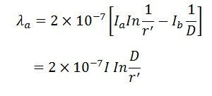 Similarly, the flux linkage with the conductor ‘b’ will be
 The inductance of the conductor ‘a’
 Similarly, the inductance of conductor ‘b’
 Inductance of both the conductors is given by the formula
 The inductance of an individual conductor is one-half of the total inductance of a two-wire line.
Inductance of symmetrical three-phase line
In symmetrical three-phase line, all the conductors are placed at the corners of the equilateral triangle. Such an arrangement of conductors is also referred to as equilateral spacing. It is shown in the diagram below
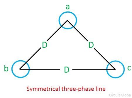 Let the spacing between the conductors be D and the radius of each conductor, r. The flux linkages of conductor a is given by the equation:
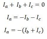
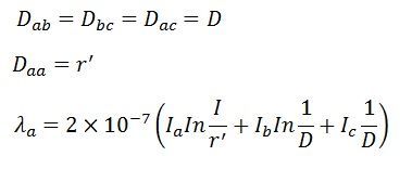 For a three-wire system, the algebraic sum of the currents in the conductors is zero.
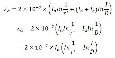 By using the formula
 ![]() The inductor of conductor, ‘a’ is
The inductor of conductor, ‘a’ is
 The inductance of conductors b and c will also be the same as that of a. The inductance of the three-phase line is equal to the two-wire line.
Inductance of unsymmetrical three-phase line
A three-phase line is said to be unsymmetrical when its conductors are situated at different distances. Such arrangement of conductors is most common in practice because of their cheapness and convenience in design and construction.
Consider a three-phase unsymmetrical line, having different spacing between their conductors where the radius of each conductor is r. It is shown in the diagram below
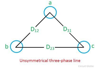 Flux linkage in ‘a’ is expressed by the formula
 Flux linkage in conductor ‘a’ due to ‘b’ is given by the formula
 Flux linkage in conductor ‘a’ due to ‘c’ is given by
 The average value of flux linkages of ‘a’ is

 The average inductance of phase a is
 Thus, it is found that the values of the inductance for the three phases are equalized by transpositions.




sir what is called r’ in total inductance formula L=2×10^-7ln R÷r’