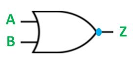
An OR gate followed by a NOT gate in a cascade is called a NOR gate. In other words, the gate which provides a high output signal only when there are low signals on the inputs such type of gate is known as NOR gate.
The logic symbol of the gate is shown below:
 The logic circuit of the gate is shown below:
 From the logic circuit of the NOR gate, the output can be expressed by the equation shown below. The below equation is read as “Z equals NOT A OR B”. Since the logic circuit involves an OR gate followed by an Inverter, the output can only be high when both the inputs are low.
The truth table of the NOR gate is given below:
| A | B | Z |
|---|---|---|
| 0 | 0 | 1 |
| 0 | 1 | 0 |
| 1 | 0 | 0 |
| 1 | 1 | 0 |
Hence, in NOR gate, all the inputs must be low to get high output that is when both the inputs A and B are at 0 the output will be 1. If any of the input is high, the output of the gate will be low that is 0. If both the inputs are high then also, the output will be low, i.e., 0.
