Definition: The transformer which is not disconnected from the main supply when the tap setting is to be changed such type of transformer in known as on-load tap changing transformer. The tap setting arrangement is mainly used for changing the turn ratio of the transformer to regulate the system voltage while the transformer is delivering the load.The main feature of an on-load tap changer is that during its operation the main circuit of the switch should not be opened. Thus, no part of the switch should get the short circuit.
In tap changing transformer different types of an impedance circuit are used for limiting the current during the operation of a tap changing.The impedance circuit may be resistor or reactor type, and by the impedance circuit, the tap changer can be classified as the resistor and reactor type. Nowadays the current limiting is carried out by using a pair of resistors.
Location of Tapping
The tapping is provided at the HV winding of the transformer because the high voltage winding is wound on the low-voltage winding. Also, the current in the HV winding of the transformer is smaller due to which small contacts and leads are required for tapping connections.
The tapping on the windings is taken out through the house board to separate the oil-filled compartment in which the on-load tap changer switch is housed. The tap changer is operated by a motor operated driving mechanism of local or remote control. The handle is operated for manual operation in case of an emergency.
Needs For Tapping
Frequently change in load changes the voltage of the system. The tap changing in the power transformer is mainly done for keeping the output voltage within the prescribed limit. Nowadays almost all the large power transformer is provided with on-load tap changer.
On-Load Tap Changing Transformer Using a Resistor
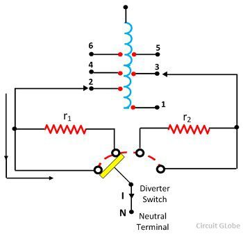
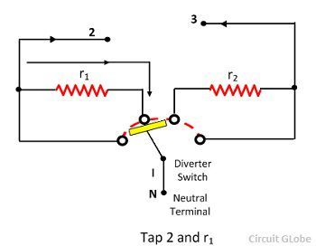
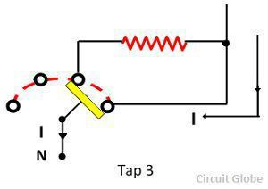
The on-load tap changing gear with the resistor transition, in which one winding is changed for each operating position as shown in the figure below. The sequence of operation during the shifting of one tap into the next is shown in the figure below. The backup main contactor is provided which short-circuit the resistors for normal operation.
The tap changer controls gear by using the push buttons. The aim of control is to maintain a given voltage level within a specified resistance or to increase it with a load to compensate for the voltage drop in the given transmission line.
On-Load Tap Changing Using a Reactor
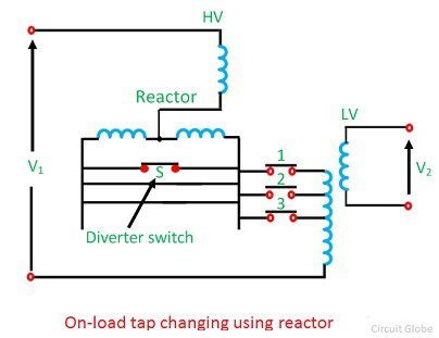
The other type of on-load tap changer is provided with a centre tapped reactor as shown in the figure below. The function of the reactor is to prevent the short circuit of the tap winding. During the normal operation, the short-circuiting switches S remains closed. The reactor prevents the flow of large values of current in any section of the primary winding when two tapping switches are closed simultaneously.
For understanding the applications of the on-load tap changer consider that the tapping switches are closed and the output voltage is minimised. For raising the output voltage, the short-circuiting switch S is opened, the second tapping switch is closed, and the first tapping switch is opened, and finally the short-circuit switch is closed.
When the short-circuiting switch is in the open position, and the two tapping switches are in closed position, the reactor is shunted between the two tapping position of the transformer windings. But the large circulating current is not established on account of its high reactance.
The line current is not affected by this reactance because the current is equally divided and flows in the opposite direction in the two halves of the reactor. The reactor carries the full current when only the one switch is closed.
The sliding contacts are so attached at the end of the reactor that makes one before other breaks and in normal operating condition both contact touches the same tapping stud. Usually, the tapping is located at the midway between the end turn of the winding to prevent the surge voltages for getting into the load ratio control elements.


What kind of training guide can be given on tap changer.