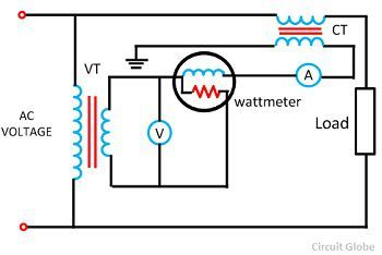
Definition – The potential transformer may be defined as an instrument transformer used for the transformation of voltage from a higher value to the lower value. This transformer step down the voltage to a safe limit value which can be easily measured by the ordinary low voltage instrument like a voltmeter, wattmeter and watt-hour meters, etc.
Construction of Potential Transformer
The potential transformer is made with high-quality core operating at low flux density so that the magnetising current is small. The terminal of the transformer should be designed so that the variation of the voltage ratio with load is minimum and the phase shift between the input and output voltage is also minimum.
The primary winding has a large number of turns, and the secondary winding has a much small number of turns. For reducing the leakage reactance, the co-axial winding is used in the potential transformer. The insulation cost is also reduced by dividing the primary winding into the sections which reduced the insulation between the layers.
Connection of Potential Transformer
The potential transformer is connected in parallel with the circuit. The primary windings of the potential transformer are directly connected to the power circuit whose voltage is to be measured. The secondary terminals of the potential transformer are connected to the measuring instrument like the voltmeter, wattmeter, etc.The secondary windings of the potential transformer are magnetically coupled through the magnetic circuit of the primary windings.
 The primary terminal of the transformer is rated for 400V to several thousand volts, and the secondary terminal is always rated for 400V. The ratio of the primary voltage to the secondary voltage is termed as transformation ratio or turn ratio.
Types of Potential Transformer
The potential transformer is mainly classified into two types, i.e., the conventional wound types (electromagnetic types) and the capacitor voltage potential transformers.
Conventional wound type transformer is very expensive because of the requirement of the insulations.Capacitor potential transformer is a combination of capacitor potential divider and a magnetic potential transformer of relatively small ratio.
The circuit diagram of the capacitor potential transformer is shown in the figure below. The stack of high voltage capacitor from the potential divider, the capacitors of two sections become C1 and C2, and the Z is the burden.
The voltage applied to the primary of the intermediate transformer is usually of the order 10kV. Both the potential divider and the intermediate transformer have the ratio and insulation requirement which are suitable for economical construction.
The intermediate transformer must be of very small ratio error, and phase angle gives the satisfactory performance of the complete unit. The secondary terminal voltage is given by the formula shown below.
Ratio and Phase Angle Errors of Potential Transformer
In an ideal potential transformer, the primary and the secondary voltage is exactly proportional to the primary voltage and exactly in phase opposition. But this cannot be achieved practically due to the primary and secondary voltage drops. Thus, both the primary and secondary voltage is introduced in the system.
Voltage Ratio Error – The voltage ratio error is expressed in regarding measured voltage, and it is given by the formula as shown below.
Where Kn is the nominal ratio, i.e., the ratio of the rated primary voltage and the rated secondary voltage.
Phase Angle Error – The phase angle error is the error between the secondary terminal voltage which is exactly in phase opposition with the primary terminal voltage.
The increases in the number of instruments in the relay connected to the secondary of the potential transformer will increase the errors in the potential transformers.
Burden of a Potential Transformer
The burden is the total external volt-amp load on the secondary at rated secondary voltage. The rated burden of a PT is a VA burden which must not be exceeded if the transformer is to operate with its rated accuracy.The rated burden is indicated on the nameplate.
The limiting or maximum burden is the greatest VA load at which the potential transformer will operate continuously without overheating its windings beyond the permissible limits. This burden is several times greater than the rated burden.
Phasor Diagram of a Potential Transformer
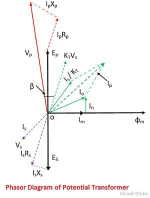
The phasor diagram of the potential transformer is shown in the figure below.
Where, Is – secondary current
Es – secondary induced emf
Vs – secondary terminal voltage
Rs – secondary winding resistance
Xs – secondary winding reactance
Ip – Primary current
Ep – primarily induced emf
Vp – primary terminal voltage
Rp – primary winding resistance
Xp – primary winding reactance
Kt – turn ratio
Io – excitation current
Im – magnetising component of Io
Iw – core loss component of Io
Φm – main flux
Β- phase angle error
The main flux is taken as a reference. In instrument transformer, the primary current is the vector sum of the excitation current Io and the current equal to the reversal secondary current Is multiplied by the ratio of 1/kt. The Vp is the voltage applied to the primary terminal of the potential transformer.
The voltage drops due to resistance and reactance of primary winding due to primary current is given by IpXp and IpRp. When the voltage drop subtracts from the primary voltage of the potential transformer, the primarily induced emf will appear across the terminals.
This primary emf of the transformer will transform into secondary winding by mutual induction and converted into secondary induced emf Es. This emf will drop by the secondary winding resistance and reactance, and the resultant voltage will appear across the secondary terminal voltage, and it is denoted by Vs.
Applications of Potential Transformer
- It is used for a metering purpose.
- For the protection of the feeders.
- For protecting the impedance of the generators.
- For synchronising the generators and feeders.
The potential transformers are used in the protecting relaying scheme because the potential coils of the protective device are not directly connected to the system in case of the high voltage. Therefore, it is necessary to step down the voltage and also to insulate the protective equipment from the primary circuit.


I am enjoying my study.
hello
please quote
Split type cast resin current transformer 15va
6300 primarty secondary 600v
Split type cast resin current transformer 15va\
3200 primary secondary 600v
Potential transformer 1 phase 480v primary
110v secondary 500va
thanks.
Thank you so much
Very good explanation
Thanks for this theory