Substation provides the energy supply for the local area in which the line is located. The main function of the substation is to collect the energy transmitted at high voltage from the generating station and then reduce the voltage to an appropriate value for local distribution and gives facilities for switching. The substation is of two types one is the simple switching type where the different connection between transmission line are made and the other is the converting stations which convert AC to DC or vice versa or convert frequency from higher to lower or lower to higher.
The substation has an additional function like they provide points where safety devices may be installed to disconnect equipment or circuit in the event of the fault. The synchronous condenser is placed at the end of the transmission line for improving the power factor and for measuring the operation at the various part of the power system. Street lighting, as well as the switching control for street lighting, can be installed in a substation.
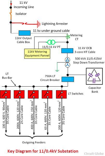
The single line diagram of an 11 KV substation is shown in the figure below. The single line diagram makes the system easy and it provides the facilitates reading of the electrical supply and connection.
Main Components of 11kV Substation
The working of the electrical equipment used in the substation is explained below in details.
- Isolator – The isolator connects or disconnects the incoming circuit when the supply is already interrupted. It is also used for breaking the charging current of the transmission line. The isolator is placed on the supply side of the circuit breaker so that the circuit breaker isolated from the live parts of the maintenance.
- Lightning Arrester – The lightning arrester is a protective device which protects the system from lightning effects. It has two terminals one is high voltage and the other is the ground voltage. The high voltage terminal is connected to the transmission line and the ground terminal passes the high voltage surges to earth.
- CT Metering – The metering CT measure and records the current when their secondary terminal is connected to the metering equipment panel.
- Step-down Transformer – The step-down transformer converts the high voltage current into the low voltage current.
- Capacitor Bank – The capacitor bank consists series or parallel connection of the capacitor. The main function of the capacitor bank is to improve the power factor of the line. It draws the leading current to the line by reducing the reactive component of the circuit.
- Circuit Breaker – The circuit breaker interrupts the abnormal or faults current to flow through the line. It is the type of electrical switch which open or closes the contacts when the fault occurs in the system.
The outgoing feeder supplies the input power to the consumer end.


Nice
Informative
I really enjoy your posts!
It was definitely informative. Your site is extremely helpful.
Very great study material
Really helpful
I think this is a really great article post. Really thank you! Keep writing.