Definition: The regulator which do not have any rotating parts, such type of regulator is called static voltage regulator. Their circuit consists apparatus like transformers, capacitors, resistors, transistors, magnetic amplifiers, etc. Such type of regulators do not have friction and wear loss ( because it does not have any rotating parts). It does not require any regular attention thus, reduces the cost of the system.
Types of Static Voltage Regulator
The static voltage regulator is superior to electromechanical regulators in respect of the accuracy of control, response, reliability and maintenance. The static voltage regulator is mainly classified into two types. They are;
- Servo Type Voltage Regulator
- Magnetic Amplifier Regulator
The types of static voltage regulator are described below in details;
1. Servo Type Voltage Regulator
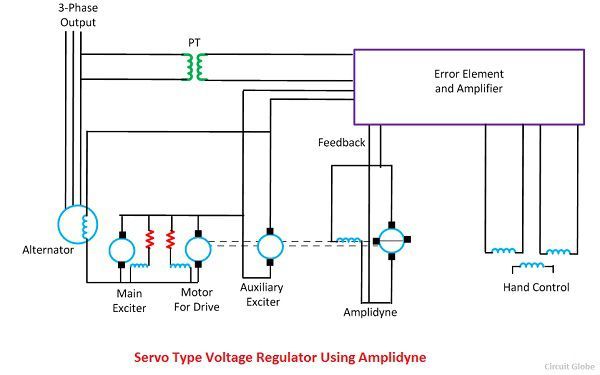
The main feature of the servo type voltage regulator is the use of the amplidyne. The amplidyne is a type of an electromechanical amplifier which amplifies the signal. The system contains the main exciter driven from the alternator shaft and an auxiliary exciter whose field winding is controlled by the amplidyne.
Both the auxiliary exciter and amplidyne are driven by a DC motor coupled to both the machines. The main exciter has a saturated magnetic circuit and hence has a rough output voltage. The armature of main and auxiliary exciter are connected in series, and this series combination excites the field winding of the alternator.
Working of Servo type Voltage Regulator
The potential transformer provides a signal which is proportional to the output signal of the alternator.The output terminals of the alternator are connected to the electronic amplifier. When the deviation occurs in the output voltage of the alternator, then the electronic amplifier sends the voltage to the amplidyne. The amplidyne output feeds the voltage to the amplidyne control field and hence alters the auxiliary exciter field. Thus, the auxiliary and the main exciter in series adjust the excitation current of the alternator.
 2. Magnetic Amplifier Regulator
The main component of the magnetic amplifiers is the steel cored coil with an additional winding energised by direct current. The additional winding is used for controlling the alternating current of relatively large power using a low power DC. The steel core of the regulator consists two identical AC winding also called the load winding. The AC winding is connected either in series or in parallel and in series with them there is a load.
 The series winding is used when the short time responses and the high voltage are required, whereas parallel winding is used for a slow response. The control winding is energised by DC. When there is no current in the load winding, then the winding of the AC has offered the highest potential and inductance to an AC potential. Due to this, the alternating current to the load is limited to a low value of the inductive reactance and the load voltage is small.
When the DC voltage is applied the DC magnetic flux passes through the core and the core approaches magnetic saturation. This decreases the inductance and impedance of the AC windings. The alternating current flow through the field winding increases as the flow of direct current through the control winding increases. Thus, the varying the magnitude of load current over a small range causes a load voltage to vary over a wide range.

very useful to any person…….
i love it…..
thank you
very good idea
It’s a very interesting explanation.