When the voltage is applied across the suspension insulator string, it is unequally distributed across the individual unit. The disc near the line conductor is extremely stressed and takes the maximum voltage in the absence of stress. The voltage distribution on insulator string determines the flashover voltage and the voltage at which the localised corona and radio interference produced.
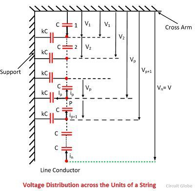
The insulator material between two metallic pins forms a capacitor of capacitance C called self-capacitance. Also, the air between the each pin and the tower form the other set of capacitors. These capacitances are called capacitances to earth.

 Let V be the voltage across the string and v1, v2,…..,vn the voltage drops across the units. 1,2,3…,n, starting from the cross arm towards the line conductor. The vn is the voltage across the ‘n’ units of the arm.
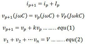
By applying KCL at the node P.
 The equation 1 and 2 are used for finding the voltage across the string. The voltage near to the line conductor is maximum and most highly stressed. The voltage goes on decreasing till the cross arm is reached.
The unit near to the line conductor is electrically stressed to its safe operating value and all the other unit on the string will remain electrically under stressed.
The string efficiency is defined as the ratio of voltage across the string to the product of the number of strings and the voltage across the unit adjacent string.
 Where, V = voltage across the whole string
n = number of insulator discs in the string
v1 = voltage across the lowest unit connected to the line conductor.
If the unit of the line conductor is about to flash over, then the whole string is about to flashover. In this condition, the string efficiency is expressed as
![]() The string efficiency decreases as the number of units increases. The voltage across the string is equal to the phase voltage, i.e., the voltage between the line and earth.
The string efficiency decreases as the number of units increases. The voltage across the string is equal to the phase voltage, i.e., the voltage between the line and earth.
Methods of Improving the String Efficiency
For the adequate performance of transmission line, it is essentials that the voltage distribution across the line should be uniform. The different methods have been attempted to get the uniform distribution of voltage along the insulators to fully utilise its strength. The following methods are explained below.
Use of Long Cross Arm
The non-uniformity in the potential distribution is due to stray capacitance between the lines and the ground. This can be reduced by using the long cross arm. The long cross arm increases the conductor spacing and the inductive reactance voltage drop. But the economy does not permit the use of very long cross arms.
Capacitance Gradings or Grading of the unit
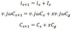
In this method, the insulators have different dimensions, and each insulator has different capacitances. The line-end unit has got the greatest capacitance, while the top unit get the smallest. By properly selecting the capacitance of the units the voltage distribution can be made uniform. The figure below shows the string of suspension insulators and the various capacitances. Let, v = voltage across each unit of the string.
Cx = self-capacitance of x the unit from the top.
Cx+1 = self-capacitances of (x+1) the unit from the top.
 This method raises the difficulties in selecting the unit for long string and it is only used for high voltage lines.
Uses of Grading Rings or Static Shielding
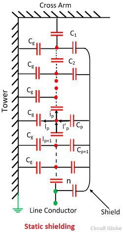
The method of using the grading or guard ring has proved to be very effective by equalising the voltage distribution. The figure below-shown the arrangement of the guard ring. The ring or shields are fitted to the bottom insulator hardware or to the clamp and connected to the line.
 The grading ring increases the stray capacitance to the line of the line-end units, and decreases the stray capacitance to earth, and thus help in making the voltage distribution uniform.Consider path link P from the top. Let C
Consider path link P from the top. Let Cp be the capacitance from the shield the pth link. Applying KCL at P.
 The grading ring is circular or oval in shape and made of galvanised tube or pipe. The combination of an arcing horn at the top and grading ring at the bottom provides a very good protection for the string against power frequency and lightning flashovers.

What is the Guard ring function in transmission? BTW nice more to learn from this site.
Great article and explanation. Thank you!