The Voltage Regulation of a Synchronous Generator is the rise in voltage at the terminals when the load is reduced from full load rated value to zero, speed and field current remaining constant. It depends upon the power factor of the load. For unity and lagging power factors, there is always a voltage drop with the increase of load, but for a certain leading power, the full load voltage regulation is zero.
The voltage regulation is given by the equation shown below: Where,
- |Ea| is the magnitude of a generated voltage per phase.
- |V| is the magnitude of rated terminal voltage per phase.
In this case, the terminal voltage is the same for both full load and no-load conditions. At lower leading power factors, the voltage rises with the increase of load, and the regulation is negative.
Determination of Voltage Regulation
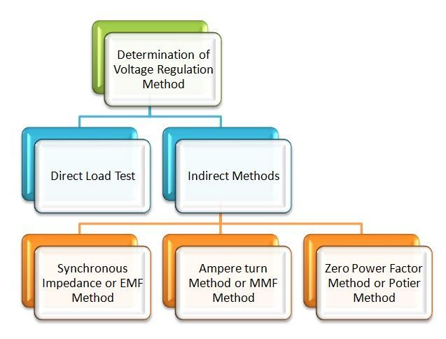
There are mainly two methods that are used to determine the regulation of voltage of smooth cylindrical rotor type alternators. They are named as a direct load test method and indirect methods of voltage regulation. The indirect method is further classified as Synchronous Impedance Method, Ampere-turn Method, and Zero Power Factor Method.
Direct Load Test
The alternator runs at synchronous speed, and its terminal voltage is adjusted to its rated value V. The load is varied until the Ammeter and Wattmeter indicate the rated values at the given power factor. The load is removed, the speed and the field excitation are kept constant. The value of the open circuit and no-load voltage is recorded.
It can be also found from the percentage voltage regulation and is given by the equation shown below:
The method of direct loading is suitable only for small alternators of the power rating less than 5 kVA.
Indirect Methods of Voltage Regulation
For large alternators, the three indirect methods are used to determine the voltage regulation they are as follows:
- Synchronous Impedance Method or EMF method.
- Ampere-turn method or MMF method of Voltage Regulation.
- Zero Power Factor method or Potier Method
This is all about voltage regulation of synchronous generator.


Draw the phasors and show it on OCC and SCC graph. thanks