The Inductance is the property of a material by virtue of which it opposes any change of magnitude and direction of electric current passing through the conductor. In other words, it is the property of the coil in which the emf is induced because of the variation of flux.
The inductance is added in the circuit through the inductor. The inductor is basically the coil of wires which concentrates the magnetic field into the circuit.
Inductance is denoted by (L), and its unit is Henry. Inductance is said to be one Henry, when a current of one ampere passes through a coil or conductor changes at a rate of per second and the voltage induces at the rate of one volt across the coil.
Contents:
- Explanation and Types of Inductors
- Series Inductor Circuit
- Parallel Inductor Circuit
- Applications of Inductor
Explanation and Types of Inductors
The inductor is formed when a wire of finite length is twisted into a coil. When the current flows through the coil, an electromagnetic field is formed. The electromagnetic field changes if the direction of flow of current changes.
This change in the electromagnetic field induces a voltage (v) across the coil and is given by the equation shown below:
Where I is the current flowing through the inductor in ampere.
The voltage across the inductor will be zero if the current flowing through it remains constant. This means that when direct, steady current flows through the inductor, it behaves as a short-circuited coil in a steady-state condition. If there is any small change in the direction or strength of the current, the inductance will appear.
If we put the value of dt as zero (dt=0) in equation (1) it is seen that for a minute change in current within zero time, gives an infinite voltage across the inductor which is not a feasible condition and thus in an inductor the current cannot be changed abruptly.
Thus, after switching the DC voltage, the inductors act as an open-circuited coil.
The power absorbed by the inductor is given by the equation shown below:
![]()
Putting the value of v from the equation (1) in equation (2) we will get power as:

The energy absorbed by the inductor is given as:

The inductor stores a finite amount of energy even though the voltage across it may be negligible.
The inductors are classified depending upon various factors like the size, core material used, type of windings, etc. The core plays an important role in the selection of the inductor.
Based on the core material the various types of the inductor are as follows:
- Ferromagnetic or iron core inductor
- Air core inductor
- Toroidal core inductor
- Laminated core inductor
- Powered core inductor
Series and Parallel Circuit connection of Inductor
Series Inductor Circuit
In the series inductor circuit, the number of inductors is connected serially in the circuit, and the same amount of current will flow in each of the inductors connected. For example, if L1, L2, L3…… inductors are connected in series and current I flow through the circuit as shown in the figure below:
 The current across inductor L1, L2, L3 will be I1, I2, I3 respectively. The value of current across each inductor will be the same.
IL1 = IL2 = IL3= IMN
The total or equivalent inductance will be given by the equation

Parallel Inductor Circuit
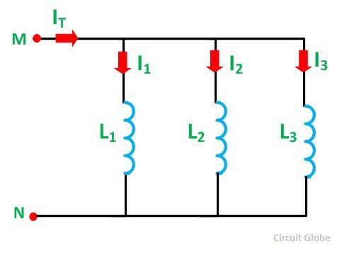
If the number of inductors is connected parallelly with each other than the circuit is known as a parallel inductor circuit. In this type of circuit, the circuit is divided into each branch of the circuit as shown in the figure below:
 Current I1 is flowing in the inductor L1, and similarly, current I2 in L2 and I3 in L3 inductor and IT is the total amount of current flowing in the circuit. The equivalent inductance is given by the equation shown below:
Applications of Inductor
Some of the uses of the Inductor are as follows
- Used in electronic equipment such as in radios
- In the communication apparatus
- Electronic testing instruments
- As an energy storage device
- In sensors, transformers, motors and various filters.
The main application of the inductors is to store energy in the form of the magnetic field.


