The currents induced in the armature conductors of a DC generator are alternating in nature. The change from a generated alternating current to the direct current applied involves the process of Commutation. When the conductors of the armature are under the north pole, the current which is induced flows in one direction. While the current flows in the opposite direction when they are under the south pole.
As the conductor passes through the influence of the north pole and enters the south pole, the current in them is reversed. The reversal of current takes place along the MNA or brush axis. When the brush span has two commutator segments, the winding element connected to those segments is short-circuited.
The term Commutation means the change that takes place in a winding element during the period of a short circuit by a brush.
Let us understand Commutation more clearly by considering a simple ring winding shown below in Figure A.
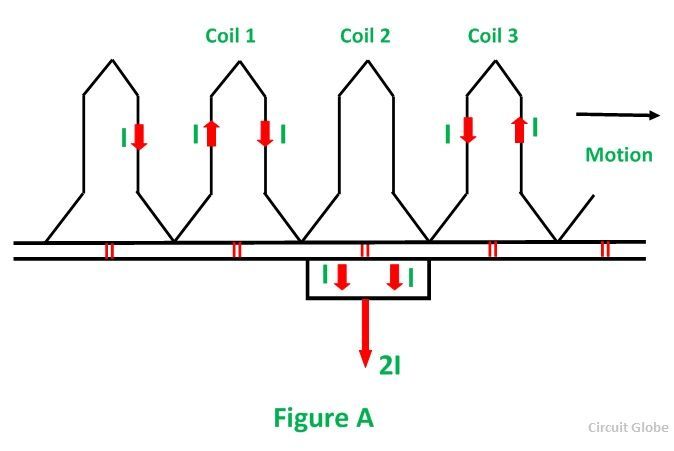 In the position shown in Figure A, the current I flowing towards the brush from the left-hand side passes around the coil in a clockwise direction.
Now consider the other figure B shown below:
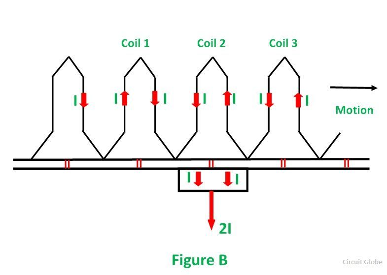 In the above figure, the position of the coil shows that the same amount of current is carried by all the coils, and the direction of the current is also similar, but the coil is too short-circuited by the brush.
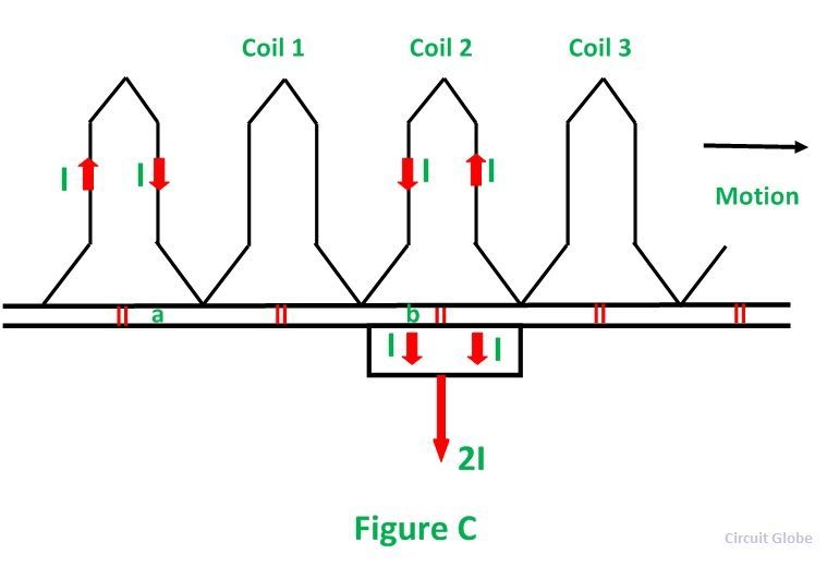
In Figure C shown below the brush makes contact with bars a and b, thereby short-circuiting coil 1. The current is still I from the left-hand side and I from the right-hand side. It is seen that these two currents can reach the brush without passing through coil 1.
 In figure D shown below, the bar (b) has just left the brush, and the short circuit of coil one has ended. It is now necessary for the current I reaching the brush from the right-hand side in the anticlockwise direction.
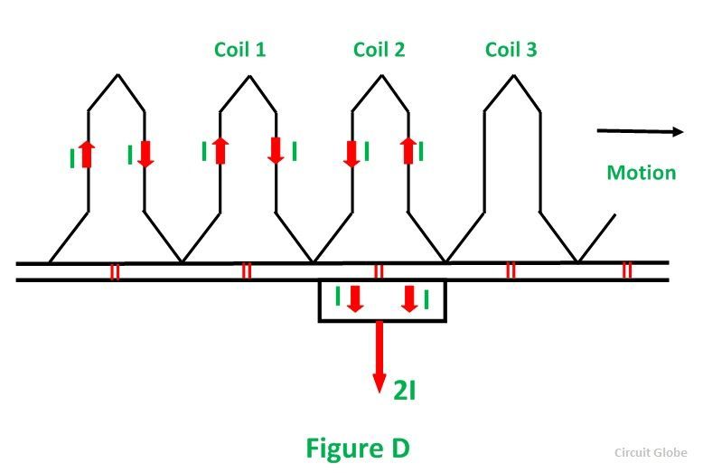 From all the above discussion, it is seen that during the period of the short circuit of an armature coil by a brush the current in the coil must be reversed and also brought up to its full value in the reverse direction. The time of the short circuit is called the period of commutation.
The figure shown below shows how the current in the short-circuited coil varies during the brief interval of the short circuit. The curve b shows that the current changes from +I to –I linearly in the commutation period. Such a commutation is called Ideal Commutation or Straight-line Commutation.
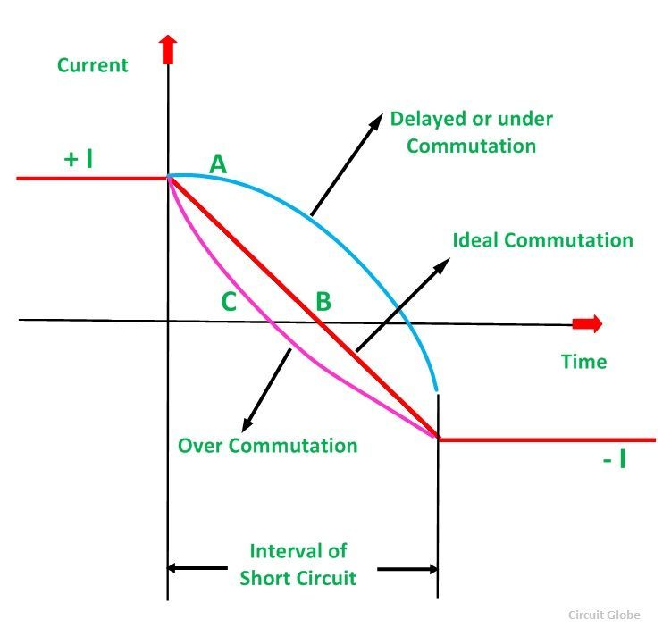 If the current through the coil 1 has not reached its full value in the position in figure D, then, since the coil 2 carrying full current, the difference between the currents through elements 2 and 1 has to jump from commutator bar to the brush in the form of a spark.
Thus, the cause of sparking at the commutator is the failure of the current in the short-circuited elements to reach the full value in the reverse direction by the end of the short circuit. This is known as under commutation or delayed commutation.
The curve of current against time in such a case is shown in figure E by the curve A. In ideal commutation curve B, the current of the commutating coils changes linearly from +I to –I during the commutation period.
In actual practice, the current in the short-circuited coil after the commutation period does not reach its full value. This is due to the fact that the short-circuited coil offers self-inductance in addition to the resistance. The rate of change of current is so high that the self-inductance of the coil sets up a back EMF, which opposes the reversal.
Since the current in the coil has to change from +I to –I, the total change is 2I. If tc is the time of short circuit and L is the inductance of the coil (= self-inductance of the short-circuited coil + mutual inductances of the neighbouring coils), then the average value of the self-induced voltage is:
This is called the reactance voltage.
The large voltage appearing between commutator segments to which the coil is connected causes sparking at the brushes of the machine. The sparking of the commutator is much harmful, and it will damage both commutator surface and brushes. Its effect is cumulative which may lead to a short circuit of the machine with an arc around the commutator from brush to brush.

