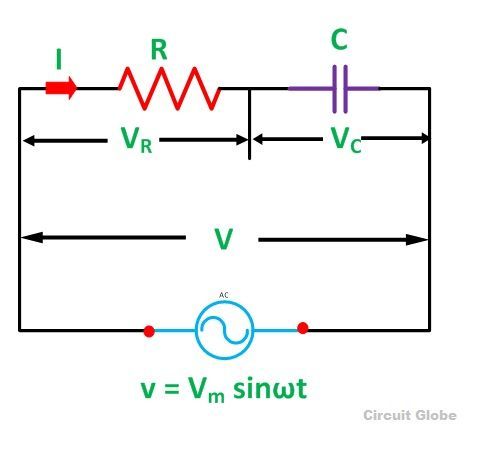
A circuit that contains pure resistance R ohms connected in series with a pure capacitor of capacitance C farads is known as RC Series Circuit. A sinusoidal voltage is applied and current I flows through the resistance (R) and the capacitance (C) of the circuit.
The RC Series circuit is shown in the figure below:
- VR – voltage across the resistance R
- VC – voltage across capacitor C
- V – total voltage across the RC Series circuit
Contents:
- Phasor Diagram of RC Series Circuit
- Steps to draw a Phasor Diagram
- Phase angle
- Power in RC Series Circuit
- Waveform and Power Curve of the RC Series Circuit
Phasor Diagram of RC Series Circuit
The phasor diagram of the RC series circuit is shown below:
Steps to draw a Phasor Diagram
The following steps are used to draw the phasor diagram of RC Series circuit
- Take the current I (r.m.s value) as a reference vector
- Voltage drop in resistance VR = IR is taken in phase with the current vector
- Voltage drop in capacitive reactance VC = IXC is drawn 90 degrees behind the current vector, as current leads voltage by 90 degrees (in the pure capacitive circuit)
- The vector sum of the two voltage drops is equal to the applied voltage V (r.m.s value).
Now,
VR = IR and VC = IXC
Where XC = I/2πfC
Z is the total opposition offered to the flow of alternating current by an RC series circuit and is called impedance of the circuit. It is measured in ohms (Ω).
Phase angle
From the phasor diagram shown above, it is clear that the current in the circuit leads the applied voltage by an angle ϕ and this angle is called the phase angle.
Power in RC Series Circuit
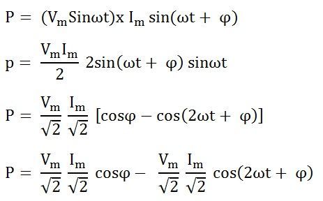
If the alternating voltage applied across the circuit is given by the equation
Therefore, the instantaneous power is given by p = vi
Putting the value of v and i from the equation (1) and (2) in p = vi
The average power consumed in the circuit over a complete cycle is given by:
Where cosϕ is called the power factor of the circuit.
Putting the value of V and cosϕ from the equation (3) the value of power will be
From the equation (4) it is clear that the power is actually consumed by the resistance only and the capacitor does not consume any power in the circuit.
Waveform and Power Curve of the RC Series Circuit
The waveform and power curve of the RC circuit is shown below:
 The various points on the power curve are obtained from the product of the instantaneous value of voltage and current.
The power is negative between the angle (180° – ϕ) and 180° and between (360° -ϕ) and 360° and in the rest of the cycle, the power is positive. Since the area under the positive loops is greater than that under the negative loops, therefore the net power over a complete cycle is positive.


Thank you very much for this great website…. . ……..
Yes this website great
Net power is positive is that mean …that power is delivering to the system?
This is most helpful website
I have a request that can you please provide a search box,it will be very useful
Thank you
@Ramanunni
On a desktop you will find the search option on the right hand side.
if you open a site on a mobile device, you need to scroll a bit further ‘below the content’ to find the search box.
Thank you so much…its very helpful and easy method for remembering 👍👌
very use full thanks a lot
This is great website for learning circuit theory
this site has improved my understanding on circuits thanks alot
Helpful
Best website 👍