Zero Power Factor Characteristic (ZPFC) of a generator is a curve of the armature terminal voltage and the field current. The machine is operated with a constantly rated armature current at synchronous speed and zero lagging power factor. The Zero Power Factor Characteristic is also called as Potier Characteristic.
For maintaining a very low power factor, the alternator is loaded by means of reactors or by an under excited synchronous motor. The shape of ZPFC is very much like that of the O.C.C.
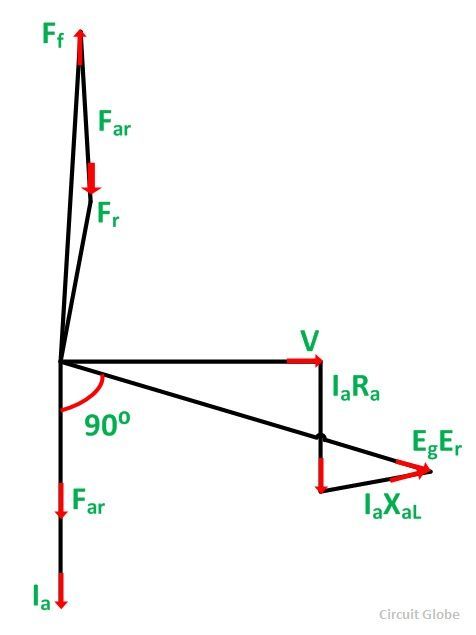
The phasor diagram corresponding to zero power factor lagging is shown below:
In the phasor diagram shown above, the terminal voltage V is taken as the reference phasor. At zero power factor lagging, the armature current Ia lags behind V by 90 degrees. IaRa is drawn parallel to Ia and IaXaL perpendicular to Ia.
Eg is the generated voltage per phase.
The phasor diagram at ZPF lagging with the armature resistance Ra neglected is shown below:
- Far is the armature reaction MMF. It is in phase with the armature current Ia.
- Ff is the MMF of the main field winding (field MMF).
- Fr is the resultant MMF.
The field MMF Ff is obtained by subtracting Far from Fr so that
 From the above phasor diagram, it is seen that the terminal voltage V, the reactance voltage drop IaXaL, and the generated voltage Eg all are in phase. Therefore, V is practically equal to the arithmetical difference between Eg and IaXaL.
![]() The three MMF phasor Ff, Fr and Far are in phase. Their magnitudes are related by the equation shown below:
The three MMF phasor Ff, Fr and Far are in phase. Their magnitudes are related by the equation shown below:
![]() The above two equations, i.e. equation (1) and (2) forms the basis for the Potier triangle.
The above two equations, i.e. equation (1) and (2) forms the basis for the Potier triangle.
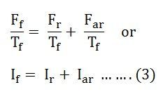
If the equation (2) is divided both sides by Tf, it is converted into its equivalent field current form. Here Tf is the effective number of turns per pole on the rotor field.
Therefore,
 From the above equation, the sum of the resultant current and the armature reaction current gives the field current.


Thanks