The Carey Foster Bridge is used for measuring the low resistance or for the comparison of two nearly equal resistances. The working principle of the Carey foster bridge is similar to the Wheatstone Bridge.
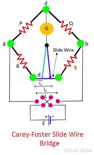
The circuit for the Carey foster bridge is shown in the figure below.
Let P, Q, R and S are the four resistors used in the bridge. The resistances of P and R are known while the R and S are the unknown resistors. The slide wire of length L is placed between the resistance R and S. The resistor P and Q are adjusted so that the ratio of P/Q is equivalent to the R/S. The ratio of the resistance is equivalent by sliding the contact on the sliding wiring.
Let l1 is the distance from the left at which the balanced is obtained. Now the R and S are interchanged, and this time the balanced is obtained by sliding the contact at the distance of l2.
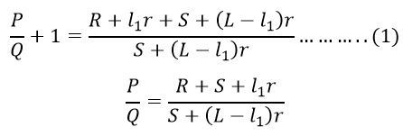
Consider the equation for first balance
The r is the resistance per unit length of the sliding wire.
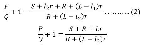
After interchanging the R and S, the balance equation of the bridge is
For the first balance equation
And for the second balance equation
From equation (1) and (2)
The difference between the resistance of S and R is obtained from a distance between the length of the slide-wire, i.e., l1 – l2 at balance condition.
Calibration of Slide Wire
The calibration of the sliding wire can be done by placing the resistance R or S in parallel with the slide wire of known resistance. Let S is known and S’ is its values when shunted by known resistance.
By solving the above equation, we get
By the help of the Carey foster bridge, the direct comparison between the resistance R and S regarding length can be done. The resistance of other components like the resistance of P, Q and sliding contact are completely eliminated.
Note: The special switch is used for interchanging the resistor S and R during the test.


Great work
Keep it up
✌✌✌