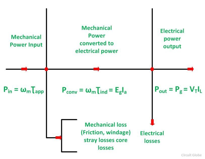
The Power Flow Diagram is used to determine the efficiency of a generator or motor. In the below figure of power flow diagram of DC Generator, it is shown that initially the mechanical power is given as an input which is converted into electrical power, and the output is obtained in the form of electrical power. There are various losses such as friction, windage, stray losses and core losses.
The power flow diagram of DC Generator is shown below:

In a DC Generator, the input is the mechanical power. The power input is given by the equation shown below.
Where,
ωm is the angular speed of the armature in radian per second.
Ʈapp is the applied torque in Newton-meter
The sum of stray losses, mechanical losses and core losses are subtracted from the input power, i.e. Pin to get the net mechanical power converted to electrical power by Electro-Mechanical conversion.
 Where Ʈe is the electromagnetic torque. The resulting electric power produced is given by the equation:
The net electrical power output is obtained by subtracting electrical power I2R losses and brush losses from Pconv.
VT is the terminal voltage, and IL is the current delivered to the load.
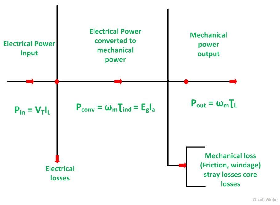
The power flow diagram of DC Motor is shown below:

From the power flow diagram of DC Motor, it is clear that the input which is given to the motor is in the electrical form which is converted into mechanical power in the second stage. The output is in the form of mechanical power.
In a DC motor, the input electrical power Pin is given by the equation shown below:
Power output is given by the equation shown below.
ƮL is the load torque in Newton-meter
Thus, the power flow diagram gives an overview, that how one form of energy is converted into another form.


GOOD