Admittance method is used for solving parallel AC circuits. The admittance shows the reliability of the electrical circuit to allow the electric current to pass through it. First of all, we must know the meanings of some terms used in the Admittance Method.
Admittance
The reciprocal of the impedance of an AC circuit is known as Admittance of the circuit. Since impedance is the total opposition offered to the flow of alternating current in an AC circuit.
Therefore, Admittance is defined as the effective ability of the circuit due to which it allows the alternating current to flow through it. It is represented by (Y). The old unit of admittance is mho (Ʊ). Its new unit is Siemens.
The circuit has an impedance of one ohm has an admittance of one Siemens. The old unit was mho.
Contents:
- Admittance
- Application of Admittance Method
- Steps for Solving Circuit by Admittance Method
- Admittance Triangle
- Conductance
- Susceptance
Application of Admittance Method
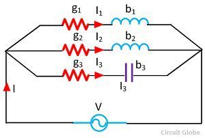
Consider the 3-branched circuit shown in the figure below. Total conductance is found by merely adding the conductance of three branches. Similarly, total susceptance is found by algebraically adding the individual susceptance of different branches.
 Total conductance G = g1 + g2 + g3 +…..
Total susceptance B = (-b1) + (-b2) + b3….
Total admittance Y = ( G2 + B2)
Total current I = VY ; Power Factor cosΦ = G / Y
Steps for Solving Circuit by Admittance Method
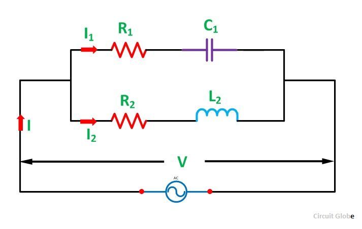
Consider a parallel AC circuit having resistance and capacitance connected in series and resistance and inductance also connected in series as shown in the figure below.
 Step 1 – Draw the circuit as per the given problem.
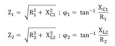
Step 2 – Find the impedance and phase angle of each branch.
Step 3 – Now, find Conductance, Susceptance and Admittance of each branch.
Step 4 – Find the algebraic sum of conductance and susceptance.
Step 5 – Find the total Admittance (Y) of the circuit.
Step 6 – Find the various branch currents of the circuit.
Step 7 – Now, find the total current I of the circuit.
Step 8 – Find the phase angle of the whole circuit.
Phase angle will be lagging if B is negative.
Step 9 – Now, find the power factor of the circuit.
Admittance Triangle
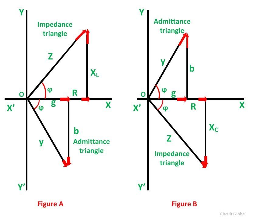
Admittance triangle is also represented similarly to impedance triangle. As the impedance (Z) of the circuit has two rectangular components, resistance (R) and reactance (X). Similarly, the admittance (Y) also has two components, conductance (g) and susceptance (b).
The admittance triangle is shown below:
Conductance
The base of the Admittance triangle is known as conductance, shown in the figure above.
 The value of conductance is always positive irrespective of the circuit parameters.
Susceptance
The perpendicular of the Admittance triangle is called Susceptance.
 Susceptance is positive for capacitive reactance as shown in the above figure (A) and is negative for inductive reactance as shown in figure (B).


