Kirchhoff’s Law: A German physicist Gustav Kirchhoff developed two laws enabling easy analysis of interconnection of any number of circuit elements. The first law deals with the flow of current and is popularly known as Kirchhoff’s Current Law (KCL) while the second one deals with the voltage drop in a closed network and is known as Kirchhoff’s Voltage Law (KVL).
The KCL states that the summation of current at a junction remains zero and according to KVL the sum of the electromotive force and the voltage drops in a closed circuit remains zero.
While applying the KCL the incoming current is taken as positive and the outgoing current is taken as negative. Similarly, While applying KVL, the rise in potential is taken as positive and the fall in potential is taken as negative.
The KVL and KCL help in finding the analogous electrical resistance and impedances of the complex system. It also determines the current flowing through each branch of the network.
Contents:
The two laws are described below
Kirchhoff’s Current Law
Kirchhoff’s Current Law states that” the algebraic sum of all the currents at any node point or a junction of a circuit is zero”.
Σ I = 0
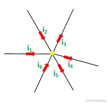 Considering the above figure as per the Kirchhoff’s Current Law:
i1 + i2 – i3 – i4 – i5 + i6 = 0 ……… (1)
The direction of incoming currents to a node is taken as positive while the outgoing currents are taken as negative. The reverse of this can also be taken, i.e. incoming current as negative or outgoing as positive. It depends upon your choice.
The equation (1) can also be written as:
i1 + i2 + i6 = i3 + i4 + i5
Sum of incoming currents = Sum of outgoing currents
According to the Kirchhoff’s Current Law, the algebraic sum of the currents entering a node must be equal to the algebraic sum of the currents leaving the node in an electrical network.
Kirchhoff’s Voltage Law
Kirchhoff’s Voltage Law states that the algebraic sum of the voltages (or voltage drops) in any closed path of a network that is transverse in a single direction is zero. In other words, in a closed circuit, the algebraic sum of all the EMFs and the algebraic sum of all the voltage drops (product of current (I) and resistance (R)) is zero.
Σ E + Σ V = 0
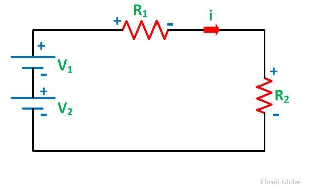 The above figure shows closed-circuit also termed as a mesh. As per the Kirchhoff’s Voltage Law:
Here, the assumed current I causes a positive voltage drop when flowing from the positive to negative potential while negative potential drop when the current flowing from negative to the positive potential.
Considering the other figure shown below and assuming the direction of the current i
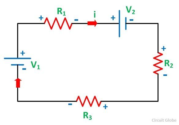
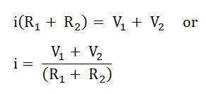
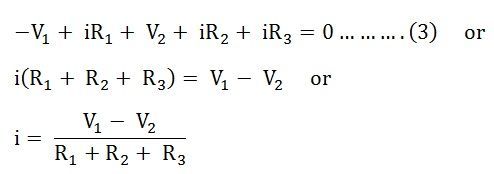
Therefore,
It is seen that the voltage V1 is negative in both the equation (2) and equation (3) while V2 is negative in the equation (2) but positive in the equation (3). This is because of the change in the direction of the current assumed in both the figures.
In figure A, the current in both the source V1 and V2 flows from negative to positive polarity while in figure B the current in the source V1 is negative to positive but for V2 is positive to negative polarity.
For the dependent sources in the circuit, KVL can also be applied. In case of the calculation of the power of any source, when the current enters the source, the power is absorbed by the sources while the source delivers the power if the current is coming out of the source.
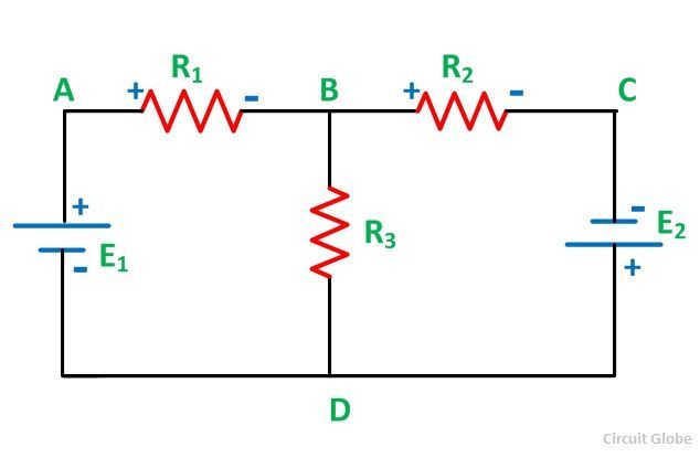
It is important to know some of the terms used in the circuit while applying KCL and KVL like node, Junction, branch, loop, mesh. They are explained with the help of a circuit shown below:
 Node
Node
A node is a point in the network or circuit where two or more circuit elements are joined. For example, in the above circuit diagram, A and B is the node points.
Junction
A junction is a point in the network where three or more circuit elements are joined. It is a point where the current is divided. In the above circuit, B and D are the junctions.
Branch
The part of a network, which lies between the two junction points is called a Branch. In the above circuit DAB, BCD and BD are the branches of the circuit.
Loop
A closed path of a network is called a loop. ABDA, BCDB are loops in the above circuit diagram shown.
Mesh
The most elementary form of a loop which cannot be further divided is called a mesh.


Good
really usefull
Superb
l
Nice explanations ……..
Good explanation
Super explanation
Really useful
We need more
Impressive ✌️
Great work.