Definition: The bridge used for the measurement of self-inductance of the circuit is known as the Maxwell bridge. It is the advanced form of the Wheatstone bridge. The Maxwell bridge works on the principle of the comparison, i.e., the value of unknown inductance is determined by comparing it with the known value or standard value.
Types of Maxwell’s Bridge
Two methods are used for determining the self-inductance of the circuit. They are
- Maxwell’s Inductance Bridge
- Maxwell’s inductance Capacitance Bridge
Maxwell’s Inductance Bridge
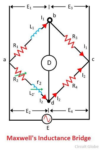
In such type of bridges, the value of unknown resistance is determined by comparing it with the known value of the standard self-inductance. The connection diagram for the balance Maxwell bridge is shown in the figure below.
Let, L1 – unknown inductance of resistance R1.
L2 – Variable inductance of fixed resistance r1.
R2 – variable resistance connected in series with inductor L2.
R3, R4 – known non-inductance resistance
The value of the R3 and the R4 resistance varies from 10 to 1000 ohms with the help of the resistance box. Sometimes for balancing the bridge, the additional resistance is also inserted into the circuit.
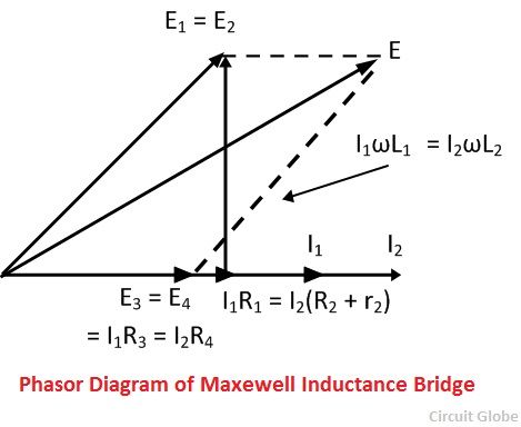
The phasor diagram of Maxwell’s inductance bridge is shown in the figure below.
Maxwell’s Inductance Capacitance Bridge
In this type of bridges, the unknown resistance is measured with the help of the standard variable capacitance. The connection diagram of the Maxwell Bridge is shown in the figure below.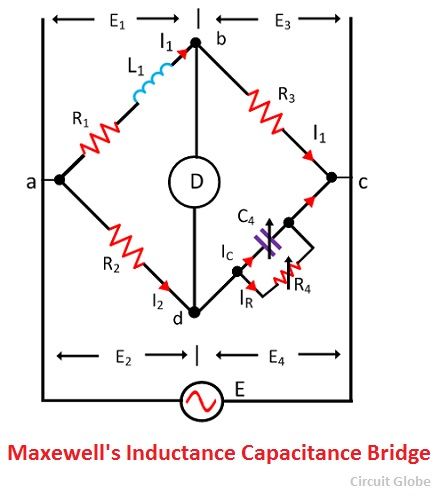
Let, L1 – unknown inductance of resistance R1.
R1 – Variable inductance of fixed resistance r1.
R2, R3, R4 – variable resistance connected in series with inductor L2.
C4 – known non-inductance resistance
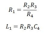
By separating the real and imaginary equation we get,
The above equation shows that the bridges have two variables R4 and C4 which appear in one of the two equations and hence both the equations are independent.
The circuit quality factor is expressed as 
Phasor diagram of Maxwell’s inductance capacitance bridge is shown in the figure below. 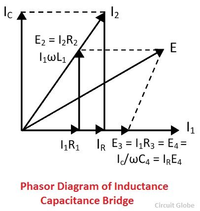
Advantages of the Maxwell’s Bridges
The following are the advantages of the Maxwell bridges
- The balance equation of the circuit is free from frequency.
- Both the balance equations are independent of each other.
- The Maxwell’s inductor capacitance bridge is used for the measurement of the high range inductance.
Disadvantages of the Maxwell’s Bridge
The main disadvantages of the bridges are
- The Maxwell inductor capacitance bridge requires a variable capacitor which is very expensive. Thus, sometimes the standard variable capacitor is used in the bridges.
- The bridge is only used for the measurement of medium quality coils.
Because of the following disadvantages, the Hays bridge is used for the measurement of circuit inductance which is the advanced form of the Maxwell’s Bridge.




Very nicely explained
Very nice explained, I passed BE by your explanation.